Canon EOS Shutter Emulation and Remote Control
Erwin Lotter, 16.09.2024
This page describes how to operate various Canon EOS models without a shutter and/or mirror. In addition to (or instead of) the emulation, an interval timer can be integrated, which can be controlled via Bluetooth from a smartphone.
Currently emulated are:
A small HC-05 module must be connected to the Arduino if a remote control for an interval timer or the PID control of a sensor cooling system, which can also be integrated, is intended.
Currently emulated are:
- 6D, 6Dmk2, 50D, 60D, 70D, 80D (shutter only),
- 550D, 600D, 650D, 700D,
- 1100D, 1200D, 1300D, 2000D
- EOS M, M3, M50, M10, M100
A small HC-05 module must be connected to the Arduino if a remote control for an interval timer or the PID control of a sensor cooling system, which can also be integrated, is intended.
Hardware
A small Arduino board that can be operated at 3.3V is suitable for easy integration into the camera. A board with an integrated USB interface is advantageous for testing and programming. From the pleasingly large range of inexpensive Arduino boards including the compatible China replicas, which are already available for around 2 euros, I have ordered these two boards:
A small Arduino board that can be operated at 3.3V is suitable for easy integration into the camera. A board with an integrated USB interface is advantageous for testing and programming. From the pleasingly large range of inexpensive Arduino boards including the compatible China replicas, which are already available for around 2 euros, I have ordered these two boards:
|
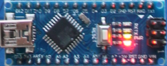
1.) Nano V3 (Mini-USB, ATmega328P, 5V) |
|
|
|
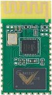
A HC-05 Bluetooth module is only required to operate the interval timer. |
|
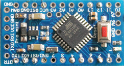
2.) Pro Mini (ATmega328 3.3V 8MHz) |
Wiring
Before you start, you should be aware that such an intervention will invalidate any warranty. Without sufficient knowledge of electronics, there is a high risk of irreparable damage to the camera!
All emulators use the coil signals to generate the control signals for the camera, which can be easily tapped into at the test points of the shutter cable. Only for the power supply voltage for some models, you need to solder directly on the EOS mainboard, but that is quite simple. (Unfortunately, the power supply of the coils can be used to power the Arduino only in the EOS M models because it is not permanent or, as with the 700D, too late.)
The Arduino outputs are isolated from the camera electronics by diodes to prevent damage to the camera electronics if the operating voltage of the Arduino is higher than 3.3V. Thus, for example, a test operation with a 5V Arduino via USB is easily possible.
The wiring differs significantly for the various camera types, with their shutters sometimes having only one holding magnet ('coil') (1100D, M), while others have two. The single and double-digit models (6D, 50D, etc.) also have a separate motor with additional control signals for the mirror.
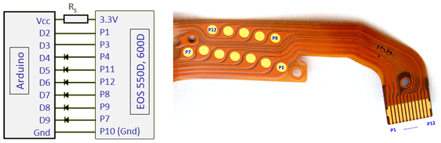
Connection scheme for the 550D and 600D, for additional models see below.
The description of the functions of the individual signal lines can be found in the control program.
The resistor 'Rs' is optional and serves to protect the mainboard against short circuits. It must not be chosen too high, otherwise the Arduino will have start-up problems. Values around 20 Ω seem well suited.
If a Bluetooth module is used, it should be omitted.
Connection diagrams for the supported cameras:
Software
An Arduino program – also called sketch – usually is passed via a serial (USB) interface to the Arduino bootloader, which permanently stores and executes the program after a reset or power-up of the Arduino. This takes about a second, however, and that’s too long for the camera, which apparently checks on start-up, whether the shutter is all right.
For testing, the Arduino can be powered with an external source (such as its own USB port). If an external power supply is already present when the camera is turned on, everything is ok.
For real-time operation, however, some models require the appropriately configured control programme (EOS-Shutter V4.0) to be transferred to the Arduino in such a way that it overwrites the bootloader and starts immediately when switched on. This is possible, for example, with a second Arduino board with a USB interface or with a special programming device. A brief description of this can be found below in the section ‘Loading Arduino boot programmes’.
Alternatively, lines that need to be low-level at startup can be connected to ground on the Arduino side with a 2.2k resistor. Then, it is sufficient to load the emulator code as a regular sketch.
Another solution is to use a faster bootloader, such as can be installed with the MiniCore package.
Emulation procedure
The Arduino is activated by a coil signal and sends the signals which the camera expects from the photocells and rotation encoders of its shutter. This usually works for all meaningful operating modes, including Live View.
During the times between the emulated shutter movements, the Arduino processor goes into a sleep state and then consumes only a few microamperes. To truly take advantage of this, however, the power LED of the Arduino must be desoldered or broken, as it otherwise consumes about 1 mA.
This also prevents light from the LED from hitting the sensor.
Installation and application of the emulator board
After the shutter removal, for which the camera has to be completely disassembled, there remains a cavity that the Arduino board can be inserted easily. You should also remove the mirror and get significantly less shading with F/5 or faster optics. As a reward, you get a camera that works completely noiseless and is no longer subject to mechanical wear.
Without a shutter, of course, the minimum exposure time is severely restricted: pictures in daylight or from the moon are no longer possible. The lower limit is determined by the duration of the reading process, which is around 1/10 second. The minimum exposure time at the top edge of the image is approx. 1/50 s and increases linearly downwards by 1/10 s - a behavior that, by the way, also limits the minimum exposure time of darks also with shutter.
This means that with one second exposure time there is a difference of about 10% between the top and bottom edges, with 10 s about 1%. In the first case, a flat field correction is advisable in any case, with 1% variation one can usually do without it. Such a level correction can also be done numerically. It is also important to note when recording flats that their exposure time is not too short, i.e. not less than e.g. 10 seconds.
Uploading a Boot-Program
An Arduino sketch can be uploaded in a way that it overwrites the bootloader and runs without it. For this purpose, a second Arduino is used as an ISP (In-System-Programmer).
Three steps are required:
1. Convert an Arduino into an ISP Programmer
First, the second Arduino - the ISP - is connected to the PC and loaded with the Programmer software. The destination board must not be connected yet! In the Arduino IDE, select „Tools > Board“ and enter the type of the ISP Arduino.
Ensure that the correct COMx interface is selected. Select „File > Examples > ArduinoISP > ArduinoISP“ and then upload as a sketch. Next, the Arduino is marked as a programmer by selecting Tools> Programmer> Arduino as ISP (not ArduinoISP!).
2. Connecting the Boards
Next, the ISP is disconnected from the USB and connected to the target arduino: Gnd-Gnd and Vcc-Vcc are connected, as are D11, D12, D13 (MOSI, MISO and SCK). D10 of the ISP goes to RST of the target. Then connect the ISP to the PC again.
3. Upload to Target
Now, the target board must be indicated as the connected board - including the correct processor and the correct clock frequency (this will not be detected automatically)! Then the desired program is opened as a sketch. The upload, however, is not done with the upload function, but with „Sketch > Upload with Programmer“ (or Shift Upload Button). With this command, the ISP loads the program as boot code into the target.